- Tinning The Soldering Tip
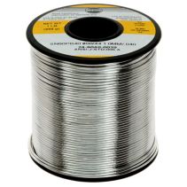
- Before use, a new soldering tip, or one that is very dirty, must be tinned. "Tinning" is the process of coating a soldering tip with a thin coat of solder. This aids in heat transfer between the tip and the component you are soldering, and also gives the solder a base from which to flow from.
- Step 1: Warm Up The Iron
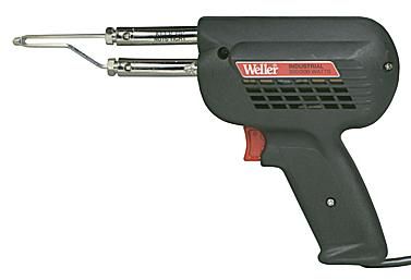
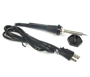
- Warm up the soldering iron or gun thoroughly. Make sure that it has fully come to temperature because you are about to melt a lot of solder on it. This is especially important if the iron is new because it may have been packed with some kind of coating to prevent corrosion.
- Step 2: Prepare A Little Space
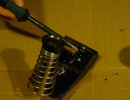
- While the soldering iron is warming up, prepare a little space to work. Moisten a little sponge and place it in the base of your soldering iron stand or in a dish close by. Lay down a piece of cardboard in case you drip solder (you probably will) and make sure you have room to work comfortably.
- Step 3: Thoroughly Coat The Tip In Solder
-
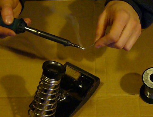
- Thoroughly coat the soldering tip in solder. It is very important to cover the entire tip. You will use a considerable amount of solder during this process and it will drip, so be ready. If you leave any part of the tip uncovered it will tend to collect flux residue and will not conduct heat very well, so run the solder up and down the tip and completely around it to totally cover it in molten solder.
- Step 4: Clean The Soldering Tip
- After you are certain that the tip is totally coated in solder, wipe the tip off on the wet sponge to remove all the flux residue. Do this immediately so there is no time for the flux to dry out and solidify.
- Step 5: You're Done!
- You have just tinned your soldering tip. This must be done anytime you replace the tip or clean it so that the iron maintains good heat transfer.
Preparing To Solder
Soldering A Printed Circuit Board (PCB)
Soldering a PCB is probably the most common soldering task an electronics hobbyist will perform. The basic techniques are fairly easy to grasp but it is a skill that will take a little practice to master. The best way to practice is to buy a simple electronics kit or assemble a simple circuit on a perf-board. Don't buy that expensive kit or dive into a huge project after only soldering a few joints.Soldering components onto a PCB involves preparing the surface, placing the components, and then soldering the joint.
- Step 1: Surface Preparation:
- A clean surface is very important if you want a strong, low resistance solder joint. All surfaces to be soldered should be cleaned well. 3M Scotch Brite pads purchased from the home improvement, industrial supply store or automotive body shop are a good choice as they will quickly remove surface tarnish but will not abrade the PCB material. Note that you will want industrial pads and not the kitchen cleaning pads impregnated with cleaner/soap. If you have particularly tough deposits on your board, then a fine grade of steel wool is acceptable but be very cautious on boards with tight tolerances as the fine steel shavings can lodge between pads and in holes.
Once you have cleaned the board down to shiny copper you can use a solvent such as acetone to clean any bits of the cleaning pad that may remain and to remove chemical contamination from the surface of the board. Methyl hydrate is another good solvent and a bit less stinky then acetone. Be aware that both these solvents can remove ink, so if your board is silk screened, test the chemicals first before hosing down the entire board.
A few blasts with compressed air will dry out the board and remove any junk that may have built up in the holes.
It also never hurts to give the component leads a quick wipe down as well, to remove glue or tarnish that may have built up over time.
- Step 2: Component Placement
- After the component and board have been cleaned, you are ready to
place the components onto the board. Unless your circuit is simple and
only contains a few components, you will probably not be placing all the
components onto the board and soldering them at once. Most likely you
will be soldering a few components at a time before turning the board
over and placing more. In general it is best to start with the smallest
and flattest components (resistors, ICs, signal diodes, etc.) and then
work up to the larger components (capacitors, power transistors,
transformers) after the small parts are done. This keeps the board
relatively flat, making it more stable during soldering. It is also best
to save sensitive components (MOSFETs, non-socketed ICs) until the end
to lessen the chance of damaging them during assembly of the rest of the
circuit.
Bend the leads as necessary and insert the component through the
proper holes on the board. To hold the part in place while you are
soldering, you may want to bend the leads on the bottom of the board at a
45 degree angle. This works well for parts with long leads such as
resistors. Components with short leads such as IC sockets can be held in
place with a little masking tape or you can bend the leads down to
clamp onto the PC board pads.
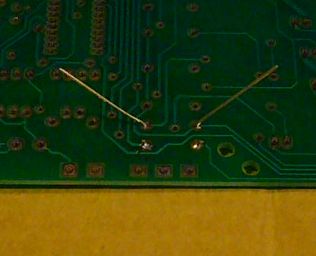
In the image below, a resistor is ready to solder and is held in place by slightly bent leads.
- Step 3: Apply Heat
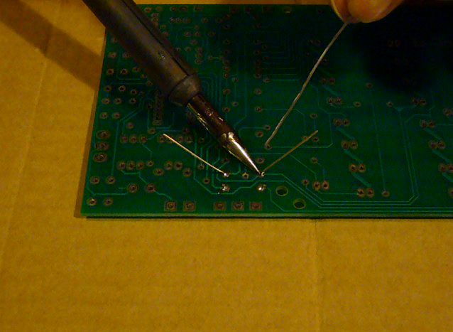
- Apply a very small amount of solder to the tip of the iron. This helps conduct the heat to the component and board, but it is not the solder that will make up the joint. To heat the joint you will lay the tip of the iron so that it rests against both the component lead and the board.
It is critical that you heat the lead and the board, otherwise the
solder will simply pool and refuse to stick to the unheated item. The
small amount of solder you applied to the tip before heating the joint
will help make contact between the board and the lead. It normally takes
a second or two to get the joint hot enough to solder, but larger
components and thicker pads/traces will absorb more heat and can
increase this time.
If you see the area under the pad starting to bubble, stop
heating and remove the soldering iron because you are overheating the
pad and it is in danger of lifting. Let it cool, then carefully heat it
again for much less time.
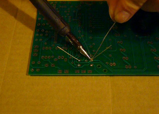
- Step 4: Apply Solder To The Joint
- Once the component lead and solder pad has heated up, you are ready to apply solder. Touch the tip of the strand of solder to the component lead and solder pad, but not the tip of the iron. If everything is hot enough, the solder should flow freely around the lead and pad. You will see the flux melt liquify as well, bubble around the joint (this is part of its cleaning action), flow out and release smoke. Continue to add solder to the joint until the pad is completely coated and the solder forms a small mound with slightly concave sides. If it starts to ball up, you have used too much solder or the pad on the board is not hot enough.
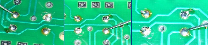
- Once the surface of the pad is completely coated, you can stop adding
solder and remove the soldering iron (in that order). Don't move the
joint for a few seconds as the solder needs time to cool and resolidify.
If you do move the joint, you will get what's called a "cold joint".
This is recognized by it's characteristic dull and grainy appearance.
Many cold joints can be fixed by reheating and applying a small amount
of solder, then being allowed to cool without being disturbed.
- Step 5: Inspect The Joint and Cleanup
- Once the joint is made you should inspect it. Check for cold joints (described a little above and at length below), shorts with adjacent pads or poor flow. If the joint checks out, move on to the next. To trim the lead, use a small set of side cutters and cut at the top of the solder joint.
After you have made all the solder joints, it is good practice to clean all the excess flux residue from the board. Some fluxes are hydroscopic (they absorb water) and can slowly absorb enough water to become slightly conductive. This can be a significant issue in a hostile environment such as an automotive application. Most fluxes will clean up easily using methyl hydrate and a rag but some will require a stronger solvent. Use the appropriate solvent to remove the flux, then blow the board dry with compressed air.- Conformal Coatings
- If the printed circuit board you just soldered is going to be used in a hostile environment where it is subjected to moisture, dirt or chemicals, it may be a good idea to apply a conformal coating such as those made by MG Chemicals. These coatings are sprayed onto a PC board to seal it against hazards of the environment. Coatings are usually lacquer, silicone or urethane based and are applied to both sides of the board once it is fully assembled and tested.
Soldering A Wire Joint or Splice
Another very common task is soldering a joint between two or more wires. Unlike soldering a PCB where the component is generally held only by the solder joint itself, a splice between wires must be physically strong before it is soldered. This usually means twisting the wires together properly and then soldering. Areas where you will see soldered wire joints are cable repairs and automotive wiring. In these cases, the joint must be insulated after soldering as well.- Step 1: Strip The Wires To Be Joined, Slip On Insulation
- Heat shrink tubing is generally the preferred method to insulate a
wire splice. There are two main types of heat shrink available; adhesive
lined and non-adhesive lined. Non-adhesive tubing forms an insulating
barrier only and thus is suitable for use only when the joint will not
be subjected to moisture, chemicals or other harsh environments.
Adhesive lined heatshrink tubing is lined with a heat sensitive adhesive
that melts to seal the joint as the tubing is heated. Thus it forms a
totally sealed joint and is used when a splice will be subjected to
moisture or other elements which can effect the joint. As an example,
you would use non-adhesive shrink tube when repairing a lamp cord, but
you would use adhesive lined tubing when installing a car stereo.
Use heat shrink tube with a diameter of approximately 1.5 times to
two times the diameter of the wires to be joined. Cut the tube to length
so that it will extend past each side of the joint by at least 0.5
inches and then slip it over one of the wire ends.
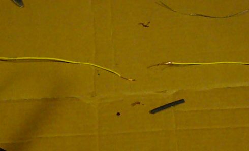
Now strip about an inch of insulation from each wire end. If you are joining rather thick wire (thicker then 12 gauge) then you may want to strip a little more insulation to make twisting the wire easier.
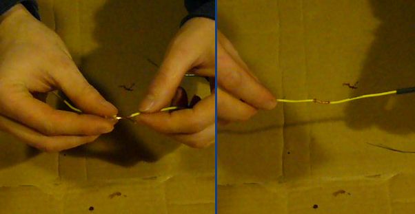
- Step 2: Twist The Wires Together
- A strong mechanical connection is necessary before the wires are to be soldered so you must twist them together. The wires will be twisted in what is referred to as a "Lineman's joint" where the wires are joined in a straight line as opposed to twisting together in a "V" shape.
- Hold the stripped ends of the wires together in an "X" shape so their
middles cross one another and then twist one of the wires along the
other wires length. Then twist the other side to match. What you will
end up with is a strong wire joint that is generally not much thicker
then the wire itself.
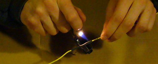
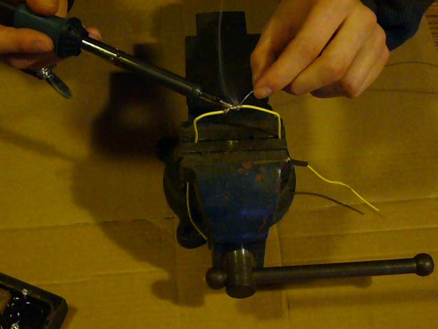
- Step 3: Apply Heat
- Apply your heat to the bottom of the wire joint and use the thicker
section of the soldering tip. If you heat up the top of the wire, you
will get a lot of heat loss since heat rises. The thicker area of the
solder iron tip will conduct more heat into the wire joint. It also
helps to slightly wet the tip of the soldering iron to further aid in
heat transfer. The thicker the wire joint, the more heat will be
required. Be careful, because on thin wires with cheap insulation you
can actually melt quite a bit of it off if you overheat the joint. Once
the joint is hot enough (a good clue is when the solder you used to wet
the tip of the iron flows into the joint) you can move on to applying
solder.
Once you have soldered a number of these joints you will be able to judge how much heat must be applied based on the thickness of the wire.
- Step 4: Apply Solder To The Joint
- With the joint fully heated, apply your solder to the joint just
above the soldering tip. If it doesn't begin to melt immediately then
you will need more heat. Once the solder begins to melt it will flow
into the joint around the soldering iron. As the solder flows, move the
tip along the wire joint while applying solder. The joint should start
to suck in the solder as it is applied. If you find that the solder is
pooling where it is touched to the joint yet it is not flowing inside,
you will need more heat. Continue adding solder until the joint is fully
covered. You should still be able to see the outlines of the individual
wire strands but no copper of the wire should be visible. If you add
too much solder to the point where the joint becomes a blob, you will
end up with a brittle joint and the excess solder will need to be
removed.
- Step 5: Clean The Flux
- If the wire joint is to be sealed or used in an area it will be
exposed to moisture, the flux must be removed. Some fluxes will absorb
moisture or other chemicals and become corrosive to the joint. While
there are flux removal chemicals available most fluxes can be cleaned up
using methyl hydrate available at any hardware store. Some are even
water soluble.
- Step 6: Insulate The Joint
- Slide the heat shrink tubing so that it evenly covers the joint and
apply heat to shrink it. Ideally, you will want a heat gun for this but a
simple lighter is acceptable as long as you keep the flame moving to
avoid burning the tubing or the wire. If you used adhesive lined heat
shrink, you need to heat the tube until it has shrunk fully around the
wire and a little of the adhesive has oozed out the ends. Non-lined
heatshrink can be heated until it tightly covers the joint. You can
overheat this stuff. If too much heat is used, then the insulation
underneath will begin to break down and may form a bubble. A bubble
could also be caused if you heat adhesive lined tubing to the point
where it starts to boil.